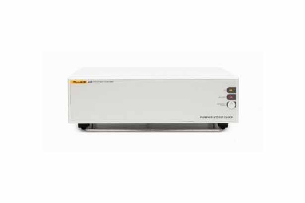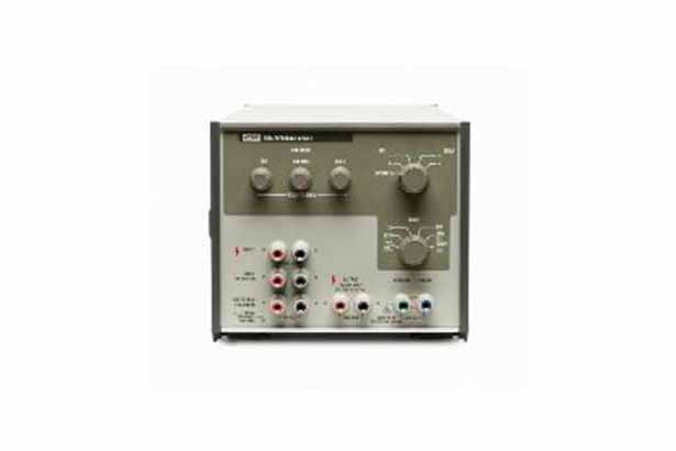

752A Reference Divider
The 752A Reference Divider sets the standard for ratio accuracy and ease of use. It offers two divider outputs, 10:1 and 100:1 with output uncertainties of less than 0.2 ppm and 0.5 ppm respectively.


The 752A Reference Divider sets the standard for ratio accuracy and ease of use. It offers two divider outputs, 10:1 and 100:1 with output uncertainties of less than 0.2 ppm and 0.5 ppm respectively.
The 752A Reference Divider sets the standard for ratio accuracy and ease of use. It offers two divider outputs, 10:1 and 100:1 with output uncertainties of less than 0.2 ppm and 0.5 ppm respectively.
Before each use, 752A reference dividers are easily calibrated with only a stable source and a null detector. The entire procedure takes only five minutes and does not require external standards.
The calibration procedure compensates for long term changes in value of the divider resistors. The upper leg of the divider is configured into three equal groups, which, when placed in parallel, form a resistor of equal value to the output resistor. These two resistors form one half of a Wheatstone bridge. The other half is composed of two calibration resistors whose positions can be interchanged in the circuit. This interchange allows correction for any difference in the values of the calibration resistors through use of the BALANCE knob on the front panel. The upper leg resistors are then matched to the output resistor with the 10:1 or 100:1 potentiometers respectively.
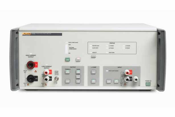
In the stand-alone divider mode, input to the divider is applied to the INPUT terminals and is switched by the MODE switch to either the 10:1 or the 100:1 position. Output from the divider is then available at the OUTPUT terminals.
When the 752A reference dividers are augmented with a 10V reference source and a null detector, the resulting system becomes a 5-decade cardinal point voltage calibrator with facilities for comparing input voltages of 1000V, 100V, 10V, 1V and 0.1V to the 10V reference. In this mode, the voltage source to be calibrated is connected to the 752A input terminals and the MODE switch reconfigures the system for each of the ranges with no manual lead changing necessary.
When the MODE switch is turned to the 752 CAL position, the 752A divider resistors are switched to form a bridge circuit with the two additional calibration resistors. Bridge excitation is supplied from the voltage source (set for an output of 20V) connected to the input terminals and the null detector is switched across the bridge to measure bridge balance.